
Light Activated Relay
This is same circuit as above with the addition of a photo resistor to trigger the flip flop instead of a push button. The bias resistor in series with photo resistor was chosen so that sufficient voltage is present at the base of the 2N3904 to supply current to the circuit in ambient lighting conditions. The circuit should toggle when the photo resistor is hit by a flashlight beam or other fast changing light source. Slow changes in light intensity will have no effect unless the light gets too bright to maintain sufficient bias for the 2N3904.
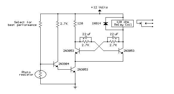
Light Activated Relay circuit
Title: Light Activated Relay
electronic circuit
Source: unknown
Published on: 2007-07-21
Reads: 923
Print version: 
Other electronic circuits and schematics from Motor, light and power control
-
12 Volt Lamp Dimmer
-
Emergency Light
-
LED Photo Sensor
-
Automatic 12 Volt Lamp Fader
-
Pulse Width Modulation DC Motor Control
-
12 Stage Neon Sequencer (NE-2 / NE-51)
-
Temperature-controlled Fan
-
73 MHz Hallogene Lamp Radio-Controlled
-
Auto Heat Limiter for Soldering Iron
-
Triple Stroboscope