Speaker Microphone
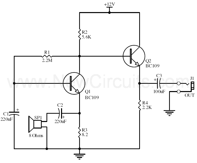
This circuits allows you to use a cheap loudspeaker as a microphone. Sound waves reaching the speaker cone cause fluctuations in the voice coil. The voice coil moving in the speakers magnetic field will produce a small electrical signal.
The circuit is designed to be used with an operating voltage between 6 and 12 volts dc. The first transistor operates in common base mode. This has the advantage of matching the low input impedance of the speaker to the common base stage, and secondly has a high voltage gain. The second stage is direct coupled and operates in emitter follower. Voltage gain is slightly less than unity, but output impedance is low, and will drive long cables.
Speech quality is not as good compared to an ordinary or ECM microphone, but quite acceptable results can be obtained. Speaker cones with diameters of 1 inch to 3 inches may be used. Speaker impedance may be 4 ohm to 64 ohm. The 8.2 ohm resistor value may be changed to match the actual speakers own impedance.
Title: Speaker Microphone
electronic circuit
Source: unknown
Published on: 2005-08-27
Reads: 1353
Print version: ![]()
Other electronic circuits and schematics from Audio
-
Headphone Monitoring Switch
-
10W Mini Audio Amplifier
-
Phono Preamplifier
-
50 Watt Amplifier
-
Ultrasonic Switch
-
3 Line Mixer
-
Loudspeaker Test Box
-
16w Bridge Amplifier
-
10W Audio Amplifier with Bass-boost
-
60W Guitar Amplifier