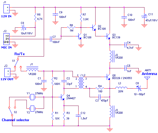
CB transmitter
TECHNICAL CHARACTERISTICS:
Tendency of catering: + 12V/1A DC
Frequency of emission at AM: ~27MHz
Force of expense: 2,5W
Materially:
The resistances are 1/4W.
| R1 | 10KW |
| R2 | 100KW |
| R3 | 39W |
| R4 | 180W |
| R5 | 4,7KW |
| R6 | 1MW |
| R7 | 3,9KW |
| C1, C9, C10 | 100nF polyester |
| C2 | 33pF ceramic |
| C3 | 470pF ceramic |
| C4 | 4,7nF polyester |
| C5 | 1nF ceramic |
| C6 | 10-60pF trimmer |
| C7 | 220nF polyester |
| C8 | 10mF/25V electrolytic |
| C11 | 47mF/25V electrolytic |
| C12 | 1,5nF ceramic |
| J1, J2, J3 | VK200 (inductor of high frequencies). |
| L1, L2 | Wires of coper (smaltwme'na) with diameter 0,4mm wrapped in plastic support of diameter 6-7mm of perjstrofjkoy' core. For the L1 you wrap 13 coils. For the L2 you wrap 4 coils. (As in the receptor CB.) |
| L3 | Wrap 20 coils cupreous wire of (0,3-0,4mm diameter) convolution round a resistance 2,2W/2W of coal. |
| Q1, Q2 | BC108 |
| Q3 | BD139 |
| Q4 | 2N4427 (it is not replaced) |
| Q5 | BD329 (or 2N3553) |
| Y1, Y2? | Crystal hails. (You can you put the so much, those who also channels that you want you emit). See here. |
| MIC | microphone with preamplifier. |
| ANT1 | Aerial for CB (For the trials is enough a piece wire of few metres but better connects a regular aerial so that does not have many stagnantly and burns the transmitter). |
| S1 | (Choice of receptor of - transmitter, if you combine the transmitter with the receptor CB, you are supplied the receptor from exit 12V OUT) |
| S2 | Switch of choice of channel. It has so much places, those who also the channels that you want pja'nete.(Kaly'tera he is mechanically connected with the S1 of receptor for simultaneous change of channels). |
Charge 50W:
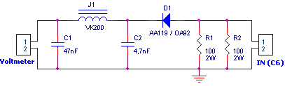
| R1, R2 | 100W/2W |
| C1 | 47nF ceramic |
| C2 | 4,7nF ceramic |
| J1 | VK200 (inductor of high frequencies). |
| D1 | Passage of germanium (AA119 or OA92 or..). |
Regulations:
For the regulation it needs a voltmeter (with needle better) and charge 50W/5W.
- Connect charge 50W in the place of aerial, with the voltmeter in the exit voltmeter.
- Be supplied the transmitter with + 12V. It will be supposed we have consumption between 0,7-1A.
- With a screwdriver we regulate the core of inductor L1/L2 and later the variable C6 until we see the biggest tendency
- We connect the microphone and speaking we observe the clue in the multimeter. If all have become right will be supposed the tendency, speaking, to go up roughly 30-35%.
Title: CB transmitter
electronic circuit
Source: www.electronics-lab.com
Published on: 2005-02-03
Reads: 1499
Print version: ![]()
Other electronic circuits and schematics from RF circuit
-
Medium range transmitter
-
Powerful AM transmitter
-
3W FM Transmitter
-
A small FM transmitter (SMD)
-
Field Strength Meter
-
4 Watt FM Transmitter
-
6 x 6 Loop Antenna
-
20dB VHF Amplifier
-
Band 2 Preamplifier
-
Micro Power AM Broadcast Transmitter