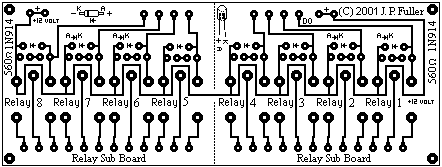
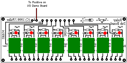
The Relay Sub Board
Attach this board to the Simplified I/O Interface Board
Use nine pieces of hookup wire (or a piece of ribbon cable) to connect corresponding points on the I/O Demonstration Board to the Relay Sub Board. Connect 12 volts DC (smoothed) to the power input points on the I/O Demonstration Board. Solder in as many relays as you intend to use, each with its associated LED, resistor and 1N914 signal diode.
LATEST UPDATE: The board is now designed so that it may be cut in two to make two separate boards, each with four relays. This should be more than adequate for most purposes.
Parts List
8 (or less) 12 volt SPDT relays
8 x 3mm red LEDs
8 x 560 ohm 1/4 watt carbon resistors
8 x 1N914 (or similar) diodes
1 x PCB Relay Sub Board
Hookup wire
Title: The Relay Sub Board
electronic circuit
Source: www.southwest.com.au
Published on: 2005-02-03
Reads: 858
Print version: ![]()
Other electronic circuits and schematics from PC related
-
The 8Way Relay Board
-
IrDA interface for your mainboard
-
DS1620 based USB Digital Thermometer
-
Opto-Isolated Stepper Motor Controller
-
8 Channel software controlled fanbus with PWM
-
Simple PC thermometer
-
Parallel Port Relay Interface
-
A Laboratory Control System for Cold Atom Experiments
-
PC based Frequency Meter
-
PC Serial Receiver (57.6K Baud / TTL & CMOS)