3-Axis Stepper Controller
This controller is designed to control (3) three unipolar stepper motors at up
to 35V@1.25A
continuous.
The controller is optimized for use with shareware CAD/CAM software (i.e. DANCAD3D).
Connections are provided for limit and home switches. Motor, switch, and power connections
are via terminal blocks. Control inputs from the PC parallel port are via pads on
the PCB. Logic power for the stepper control ICs and control input pull-ups is provided
from the motor supply
via a 7805 regulator. This should be safely usable at motor voltages up to 25V.
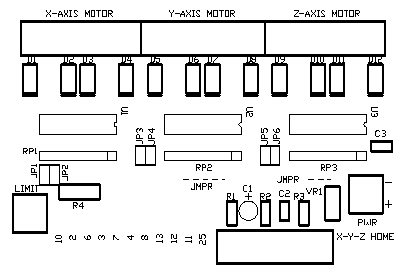
The PCB measure 3"x4" and has (4) four mounting pads. Postscript(tm) files are provided
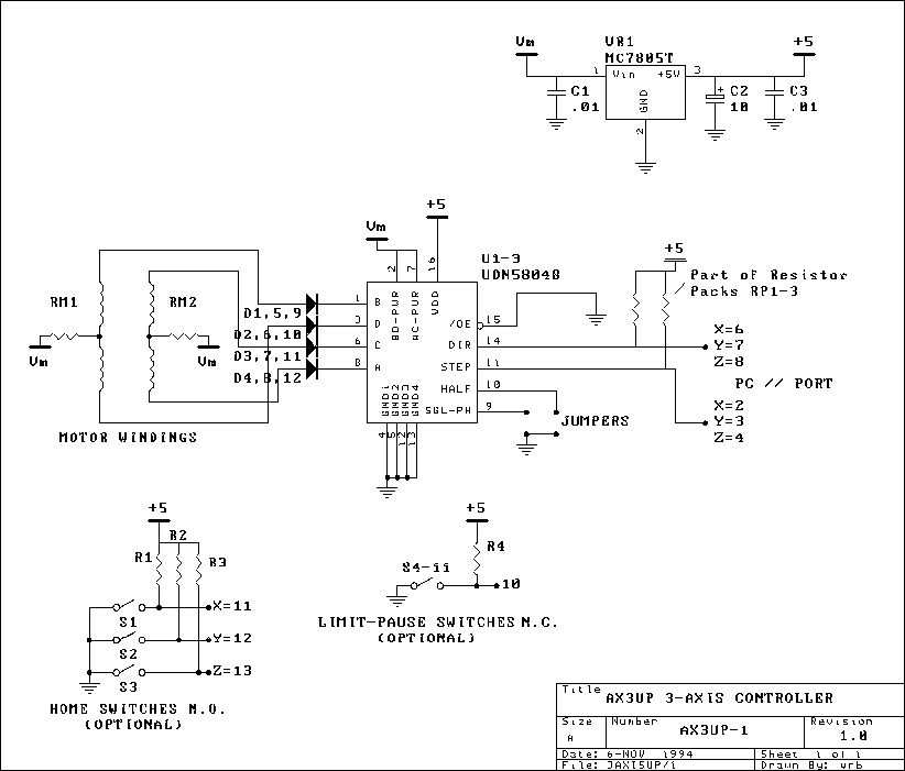
for the schematic, PCB layout, and PCB parts placement diagram. These files are
named schmatic.ps,
pcb.ps, and
overlay.ps,
respectively.
For more info on homemade CNC equipment, see the series of articles by Dan Mauch
starting in the October, 1994 issue of "Nuts & Volts".
Refer to the schematic and parts placement for connections to the PC parallel
port. While designed to be controlled from a PC, the controller can easily be
controlled from a microcontroller or even logic circuitry. All control inputs
are TTL compatible. Refer to placement diagram for power connections.
When looking at the numbers on the parts overlay, the control connections are
as follows:
10 - limit and pause switch: this connection, specifically for PC connections,
is used to monitor normally closed (N.C.) limit switches. When one of these switches,
connected in series, opens, it generates an interrupt in the PC that can be used
to stop the motors. IF YOU CHOOSE NOT TO USE LIMIT SWITCHES THIS INPUT MAY HAVE
TO BE SHORTED SO IT DOESN'T SEE AN "OPEN SWITCH".
2, 3, 4 - x-, y-, and z-axis step inputs, respectively.
6, 7, 8 - x-, y-, and z-axis direction inputs, respectively. Direction polarity
depends on the motor connections. (to switch direction polarity, simply reverse
the motor connections
end-for-end)
13, 12, 11 - these PC connections are used to bring the controlled machinery (i.e.
X-Y table) to a "home" position. Normally open (N.O.) switches are used here.

Parts List for 3-Axis Stepper Controller
(1) PC Board: CW Technology AX3UP-PCB ($18) or make.
(3) U1-3 UCN5804B Stepper Controller IC: CW Technology ($7) or Pure Unobtanium
(12) D1-12 200V/1A Fast Recovery Rectifiers: Digi-Key 1N4935CT-ND
(1) VR1 7805 5V Regulator: various
(4) R1-4 4.7K ohm, 1/4W resistors: various
(2) C2,3 0.01 uF, 63V Monolithic capacitor: Digi-Key P4914-ND
(1) C1 10uF, 25V Miniature Electrolytic: Digi-Key P813
(3) Slide-on sink for U2: Digi-Key HS125-ND
(3) RP1-3 Resistor Network: Digi-Key 770-81-R-4.7K
(14) 2-pos. Terminal blocks (optional): Digi-Key ED-1601-ND
(1) Parallel port cable: various
Suppliers:
CW Technology (me) ALL ABOVE PRICES INCLUDE SHIPPING
7328 Timbercreek Ct
Reynoldsburg, OH 43068-1181
800-547-7479 - COD Orders Only 24 hrs. ($5 COD Charge applies)
cwtech@infinet.com
Sorry, no MC/Visa at this time.
Digi-Key
701 Brooks Ave
Thief River Falls, MN 56701
1-800-344-4539
Pure Unobtanium
13109 Old Creedmoor Rd
Raleigh, NC 27613
919-676-4525
![]() Also check the conversation about this project at the community. Post you questions
here.
Also check the conversation about this project at the community. Post you questions
here.
Questions and comments can be sent to cwtech@infinet.com.
Title: 3-Axis Stepper Controller
electronic circuit
Source: www.electronics-lab.com
Published on: 2005-02-03
Reads: 3043
Print version: ![]()
Other electronic circuits and schematics from PC related
-
Build your own printer cable LCD Display
-
Reading Data From The Parallel Port
-
Stepper motor controller
-
RJ45 Network card to IR communication
-
DS1621 pc thermometer
-
Opto-Isolated Stepper Motor Controller
-
DS1620 based USB Digital Thermometer
-
A Worked Stepping Motor Example
-
PC based Frequency Meter
-
The 8Way Relay Board

