Boolean algebra
Inputs to and outputs from digital circuits are denoted by letters of the alphabet A, B C and so on. Each input or output, as we have seen, can be in one of two states: 0 or 1. So, for example, we can say A = 1, B = 0, C = 1 and so on.
Now, of course, in any digital system, the output will be dependent on the input (or inputs). Let’s take as an example the simplest logic gate — the inverter — we’ve already seen in operation. Figure 10.9 shows it again, along with its truth table, only this time the truth table uses standard Boolean algebra letters A and B. If A = 1, then we can see that B = 0. Conversely, if A = logic 0, then B = 1.
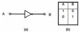
Figure 10.9 (a) the symbol for an inverter or NOT gate; (b) its truth table
In Boolean algebra we write this fact much more succinctly, as:

where the bar above the letter B indicates what is called a NOT function — that is, the logic state of A is NOT the logic state of B. Alternatively, we could equally well say that B is NOT A, that is:

Both Boolean statements are true with respect to an inverter, and are actually synonymous. Incidentally, inverters are often called NOT gates for this very reason.
You should be able to see that the Boolean statements for a gate simply allow us a convenient method of writing down the way a gate operates — without the necessity of drawing a gate symbol or forming the gate’s truth table. No matter how complex a gate circuit is, if we reduce it to a Boolean statement, it becomes simple to understand.
<< Other logic circuits