Load lines
It’s important to remember that although a diode characteristic curve is non-linear and non-ohmic, so that it doesn’t abide by Ohm’s law throughout its entire length, it does follow Ohm’s law at any particular point on the curve. So, say, if the voltage across the diode whose characteristic curve is shown in Figure 7.1 is 0V8, so the current through it is about 80 mA (check it yourself) then the diode resistance is:
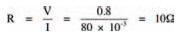
as defined by Ohm’s law. Any change in voltage and current, however, results in a different resistance.
Generally, diodes don’t exist in a circuit merely by themselves. Other components e.g. resistors, capacitors, and other components in the semiconductor family, are combined with them. It is when designing such circuits and calculating the operating voltages and currents in the circuits that the use of diode characteristic curves really come in handy. Figure 7.4 shows as an example a simple circuit consisting of a diode, a resistor and a battery. By looking at the circuit we can see that a current will flow. But what is this current? If we knew the voltage across the resistor we could calculate (from Ohm’s law) the current through it, which is of course the circuit current. Similarly, if we knew the voltage across the diode we could determine (from the characteristic curve) the circuit current. Unfortunately we know neither voltage!
We do know, however, that the voltages across both the components must add up to the battery voltage. In other words:

it’s a straightforward voltage divider). This means that we can calculate each voltage as being a function of the battery voltage, given by:
and
Now, we know that the voltage across the diode can only vary between about 0 V and 0V8 (given by the characteristic curve), but there’s nothing to stop us hypothesising about larger voltages than this, and drawing up a table of voltages which would thus occur across the resistor. Table 7.1 is such a table, but it takes the process one stage further by calculating the hypothetical current through the resistor at these hypothetical voltages.
From Table 7.1 we can now plot a second curve on the diode characteristic curve, of diode voltage against resistor current. Figure 7.6 shows the completed characteristic curve (labelled Load line R=60R). The curve is actually a straight line — fairly obvious, if you think about it, because all we’ve done is plot a voltage and a current for a resistor, and resistors are ohmic and linear. Because in such a circuit as that of Figure 7.4 the resistor is known as a load i.e. it absorbs electrical power, the line on the characteristic curve representing diode voltage and resistor current is called the load line.
Where the load line and the characteristic curve cross is the operating point. As its name implies, this is the point representing the current through and voltage across the components in the circuit. In this example the diode voltage is thus 1 V and the diode current is 33 mA at the operating point.
Table 7.1 Diode characteristics
If you think carefully about what we’ve just seen, you should see that the load line is a sort of resistor characteristic curve. It doesn’t look quite like those of Figure 7.3, however, because the load line does not correspond to resistor voltage and resistor current, but diode voltage and resistor current — so it’s a sort of inverse resistor characteristic curve — shown in Figure 7.5.
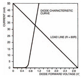
Figure 7.5 Load line from Table 1 results
The slope of the load line (and thus the exact position of the circuit operating point) depends on the value of the resistor. Let’s change the value of the resistor in Figure 7.4 to say 200 Ω. What is the new operating point? Draw the new load line corresponding to a resistor of value 200 Ω on Figure 7.5 to find out. You don’t need to draw up a new table as in Table 7.1 — we know it’s a straight line so we can draw it if we have only two points on the line. These two points can be when the diode voltage is 0 V (thus the resistor voltage:
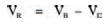
equals the battery voltage), and when the diode voltage equals the battery voltage and so the resistor current is zero. Figure 7.6 shows how your results should appear. The new operating point corresponds to a diode voltage of 0V8 and current of about 11 mA.We’ll be looking at other examples of the uses of load lines when we look at other semiconductor devices in later chapters.
Figure 7.6 This shows the new load line for a resistor of 200 Ω
<< Maths