Experiment
Using the multi-meter in our first experiment — to measure a resistor’s resistance — we will now go through the procedure step-by-step, so that you get the hang of it.
The circuit built on breadboard is shown in Figure 2.3. Being only one resistor it’s an extremely simple circuit. So simple that we are sure you would be able to do-it-yourself without our aid, but we might as well start off on a good footing and do the job properly — some of the circuits we’ll be looking at in following chapters will not be so simple.
If you have an analogue multi-meter, you have to adjust it so that the reading is accurate. Step-by-step, this is as follows:
- Turn the switch to point to a resistance range (usually marker OHM ×1K, or similar).
- Touch the multi-meter probes together — the pointer should swing around to the right.
- Read the resistance scale of the multi-meter — the top one on our multi-meter marked OHMS, where the pointer crosses it — it should cross exactly on the number 0.
- If it doesn’t cross at 0, adjust the multi-meter using the zero adjust knob (usuallu marked 0ΩADJ).
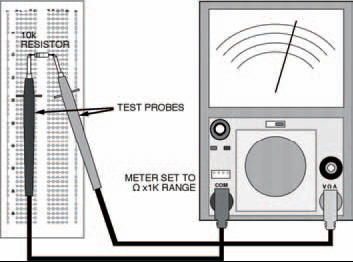
Figure 2.3 About the simplest circuit you could have: a single resistor and a multi-meter. The multi-meter takes the place of a power supply, and the circuit’s job is to test the resistor!
What you’ve just done is the process of zeroing the multimeter. You have to zero the multi-meter every time you use it to measure resistance. You also have to do it if you change resistance ranges. On the other hand, you never have to do it if you use your multi-meter to measure current or voltage, only resistance, or if you have a digital multi-meter.
You see, measurement of resistance relies on the voltages of cells or a battery inside the multi-meter. If a new cell is in operation, the voltage it produces may be, say, 1.6 V. But as it gets older and starts to run down, the voltage may fall to, say, 1.4 V or even lower. The zero adjustment allows you to take this change in cell or battery voltage into account and therefore make sure your resistance measurement is correct. Clever, eh?
Measurement of ordinary current and voltage, on the other hand, doesn’t rely on an internal cell or battery at all, so zero adjustment is not necessary.
Now let’s get back to our experiment. Following the diagram of Figure 2.3:
- Put a 10 k resistor (brown, black, orange bands) into the breadboard.
- Touch the multi-meter leads against the leads of the resistor (it doesn’t matter which way round the multi-meter leads are).
- Read-off the scale at the point where the pointer crosses it. What does it read? It should be 10.
But how can that be? It’s a 10 k resistor, isn’t it? Well, the answer’s simple. If you remember, you turned the multi-meter’s range switch to OHM ×1K, didn’t you? Officially, this should be OHM ×1k, that is, a lower case k. This tells you that whatever reading you get on the resistance scale you multiply by 1 k, that is 1000. So the multi-meter reading is actually 10,000. And what is the value of the resistor in the breadboard — 10 k (or 10,000 Ω), right!
Hint:
Resistor colour-code
Resistance values are indicated on the bodies of resistors in one of two ways: in actual figures, or more usually by a colour code. Resistors using figures are usually high precision or high wattage types that have sufficient space on their bodies to print characters on. Colour coding, on the other hand, is the method used on the vast majority of resistors — for two reasons. First, it is easier to read when components are in place on a printed circuit board. Second, some resistors are so small it would be impossible to print numbers on them — let alone read them afterwards.
Depending on the type of resistor, the colour code can be made up of four or five bands printed around the resistor’s body (as shown below). The five-band code is typically used on more accurate resistors as it provides a more precise representation of value. Usually, the four-band code is adequate for most general purposes and it’s the one you’ll nearly always use — but you still need to be aware of both! Table 2.1 shows both resistors and lists the colours and values associated with each band of both four-band and five-band colour codes.
Hint:
The bands grouped together indicate the resistor’s resistance value, while the single band indicates its tolerance.
The first band of the group indicates the resistor’s first figure of its value. The second band is the second figure. Then, for a four-band coded resistor the third band is the multiplier. For a five-band coded resistor the third band is simply the resistor’s third figure, while the fourth band is the multiplier. For both, the multiplier is simply the factor by which the first figure should be multiplied by (or simply the number of noughts to add) to obtain the actual resistance.
As an example, take a resistor coded red, violet, orange, silver. Looking at Table 2.1, we can see that it’s obviously a four-band colour coded resistor, and its first figure is 2, second is 7, multiplier is x1000, and tolerance is В±10%. In other words, its value is 27,000 Ω, or 27 k.
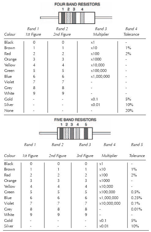
Table 2.1 Resistor colour code
In practice, you might find that your resistor’s measurement isn’t exactly 10 k. It may be, say, 9.5 k or 10.5 k. This is due, of course, to tolerance. Both the resistor and the multi-meter have a tolerance: indicated on the resistor by the last coloured band: the multimeter’s is probably around ± 5%. Chances are, though, you’ll find the multi-meter reading is as close to 10 k as makes no difference.
Now you’ve seen how your multi-meter works, you can use it to measure any other resistors you have, if you wish. You’ll find that lower value resistors need to be measured with the range switch on lower ranges, say Ω x 100. Remember — if you have an analogue multi-meter — every time you intend to make a measurement you must first zero the multi-meter. The process may seem a bit long-winded for the first two or three measurements, but after that you’ll get the hang of it.
<< The first circuit