The first circuit
We’ve done a lot of talking up to now, and not much doing, but now it’s time to use your breadboard to build your first circuit. Well, to be truthful it’s not really a circuit — it’s just a single resistor stuck into the breadboard so that we can experiment with it.
The experiments in this chapter are all pretty simple ones, measuring the resistances of various resistors and their associated circuits. But to measure the resistances we need the other essential tool I mentioned earlier — the multi-meter. Strictly speaking a multi-meter isn’t just a tool used in electronics, it’s a complete piece of equipment. It can be used not only to measure resistance of resistors, but also voltage and current in a circuit. Indeed, some expensive multi-meters may be used to measure other things, too. However, you don’t need an expensive one to measure only the essentials (and some non-essentials, too).
Hint:
The multi-meter you buy and use is not important – as long as it meets a certain specification it will do the job nicely. This specification is below.
Note that any modern multi-meter should meet this specification. The specification represents just the absolute minimum you should check for, and was originally drawn up for use when buying an analogue multi-meter (ie, one with a pointer). Most modern multi-meters are of a digital nature (ie, with a digital readout) and so will usually greatly exceed the minimum specification.
While it’s impossible for me to comment on how you intend using your multi-meter, so it’s impossible for me to tell you which one to buy. On the other hand, it is possible for me to recommend a few specifications which you should try to match or better, when you buy your multi-meter. This is simply to ensure that your multi-meter will be as general-purpose as possible, and will perform measurements for you long after you progress from being a beginner in electronics to being an expert. The important points to remember are:
- it must have a sensitivity of at least 20 kΩ V-1 on d.c.ranges. (d.c. stands for direct current).
- it must have an accuracy of no worse than В±5%.
- its smallest d.c. voltage range should be no greater than 1 V.
- its smallest current range should be no greater than 500 μA.
- it should measure resistance in at least three ranges.
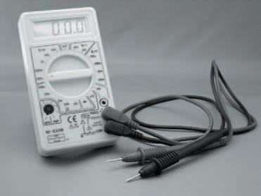
Photo 2.5 A multi-meter — the one used throughout this book — although any multi-meter with at least the specification given will do
In practice, just about any modern multi-meter will meet and exceed this specification. Only older style analogue multi-meters may fall below it — digital multi-meters almost always exceed it.
Using, a multi-meter is fairly simple. It will probably have a switch on the front, which turns so that you may select which range of measurement you want. When you have connected the multi-meter up to the circuit you wish to measure (a pair of leads should be supplied with the multi-meter) the readout will display the measurement or (on an older analogue multi-meter), the pointer of the multi-meter moves and you can read-off the measured value on the scale underneath the pointer. At the ends of the multi-meter leads are probes which allow you to connect the multi-meter to the circuit in question.
<< ICs