Pinewood Derby Finish Line Lamps
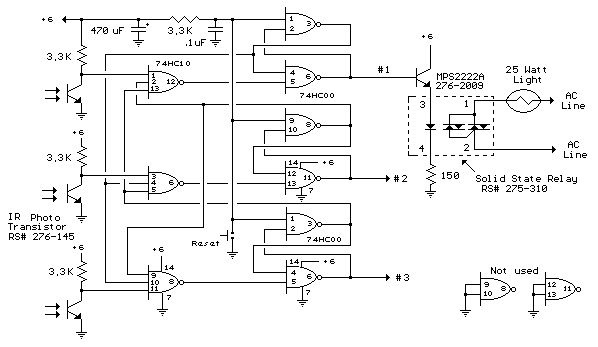
The finish line circuit below detects the first of three cars to cross the line and illuminates a 25 watt 120 VAC lamp indicating the winning lane. Three photo transistors are used which can be embedded into the track with a light shining down onto the finish line so that as the car crosses over the sensor, the light is blocked, activating the relay and lighting the lamp for the appropriate track. The light source should be an incandescent type, florescent lights may not work due to low infra-red content. The circuit was tested using a 100 watt incandescent light fixture about 3 feet above the photo transistors.

Pinewood Derby Finish Line Lamps circuit
The photo transistors are connected so that a logic low (0 volts) normally appears at the input to a NAND gate and as a car crosses the line blocking light to the transistor the logic level will move high (+6 volts). The resulting logic low level from the output of the gate (3 input NAND) is fed to a SET/RESET latch made from two dual input NAND gates (1/2 of a 74HC00) the (logic high) output of which controls the MPS2222A buffer transistor and solid state relay. The inverted output of the latch (logic low) is connected back to the remaining two (3 input NAND gate) inputs locking them out. Two extra 74HC00 gates are not used and should have their inputs (pins 9,10,12,13) connected to ground to avoid possible oscillation. The circuit is reset with a momentary push button connected to the reset side of each latch. The reset button may need to be pressed after power is first applied. Components for the circuit may be obtained from Radio Shack, however the RSU numbers may need to be special ordered or obtained from another source. The 74HC00 and 74HC10 are CMOS parts and should be handled carefully to avoid possible damage from static electricity. You may want to use IC sockets so the wiring can be completed before the ICs are inserted into the sockets. You can briefly touch a grounded surface (computer chassis or other metal ground surface) just before handling CMOS circuits to reduce the possibility of damage from static electricity.
Notes:
All ground symbols are connected to the negative side of the battery.
All +6 points are connected to the positive side of the battery.
Transistors and relays for #2 and #3 lights are not shown but are connected
the same as shown for #1.
A small LED may be substituted for the solid state relay (pins 3,4) for
testing the circuit before the relays are installed.
Pins 8,6 and 12 of the 74HC10 should read +6 volts after reset is pressed
and light is shining on the photo transistors.
Pins 1,9 of the top 74HC00 and pin 1 of the lower 74HC00 should read +6
volts with the reset button released. The same pins should read 0 volts with
the button pressed.
Pins 2,6,10,11 of upper 74HC00 and 2,6 of lower should read 0 volts after
reset button is released and photo transistors are illuminated.
Pins 3,4,8,12 of upper 74HC00 and pins 3,4 of lower should read +6 after
reset button is released.
Pins 9,10,12,13 of lower 74HC00 should be grounded
Parts List:
Two - 74HC00 Quad, 2 input NAND gates - RSU 10880045 - $0.89 ea.
One - 74HC10 Triple 3 input NAND gate - RSU 10880540 - .89 ea.
Three - IR photo transistors - 276-145 - .99 ea.
Three - MPS2222A NPN transistors - 276-2030 - .99 ea.
Three - 1/4 watt 150 ohm resistors - 271-1312 - .49/5
Three - Solid state relays, 3 Amp/120VAC - 275-310 - 6.99 ea.
Four - 1/4 watt 3.3K resistors - 271-1328 - .49/5
One - 470 uF/16 volt capacitor - 272-957 - .99 ea.
One - 0.1uF capacitor - 272-135 - .69 ea.
One - Momentary (normally open) push button - 275-1556 or 275-1571
One - 6 volt lantern battery or regulated power supply.
Three - 25 to 60 watt 120VAC lamps and sockets.
Title: Pinewood Derby Finish Line Lamps
electronic circuit
Source: unknown
Published on: 2007-07-21
Reads: 1622
Print version: ![]()
Other electronic circuits and schematics from Games and entertainment
-
3V LED Chaser
-
JAM(Just A Minute) Circuit
-
Game Show Indicator Lights (Who's First)
-
TV remote control Blocker
-
The flashing Heart
-
6V Ultra-Bright LED Chaser
-
The Millipede
-
Electronic Scoring Game
