A simple electronic buzzer
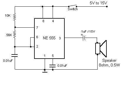
This very simple circuit just uses a couple of resistors, a capacitor and the
easily available 555 timer IC.
The 555 is setup as an astable multivibrator operating at a frequency of about
1kHz that produces a shrill noise when switched on. The frequency can be changed
by varying the 10K resistor.
Title: A simple electronic buzzer
electronic circuit
Source: www.electronic-circuits-diagrams.com
Published on: 2005-02-01
Reads: 1299
Print version: ![]()
Other electronic circuits and schematics from Security and other sensors and detectors
-
Car anti theft wireless alarm
-
Water Level Indicator with alarm
-
IR transceiver 1.0
-
Light switch
-
Voice activated switch
-
Big Ben Sound
-
Frost Alarm
-
Low Voltage Alarm
-
Emergency Light & Alarm
-
Metal Detector