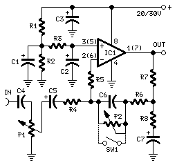
Stereo Preamplifier with Bass-boost
High Quality, simple design
20 to 30V supply

Parts:
P1_________________10K Log.Potentiometer (Dual-gang for stereo)
P2________________100K Log.Potentiometer (Dual-gang for stereo) (See Notes)
R1,R2_____________100K 1/4W Resistors
R3,R6______________15K 1/4W Resistors
R4_________________10K 1/4W Resistor
R5_________________22K 1/4W Resistor
R7__________________1K 1/4W Resistor
R8________________560R 1/4W Resistor
C1,C2,C5____________2µ2 63V Electrolytic Capacitors
C3________________470µF 35V Electrolytic Capacitor
C4__________________1µF 63V Polyester Capacitor
C6_________________47nF 63V Polyester Capacitor
C7_________________22µF 25V Electrolytic Capacitor
IC1_______________TL072 Dual BIFET Op-Amp
SW1________________DPST Switch (Optional, see Notes)
Comments:
This preamplifier was designed to cope with CD players, tuners, tape recorders etc., providing a gain of 4, in order to drive less sensitive power amplifiers. As modern Hi-Fi home equipment is frequently fitted with small loudspeaker cabinets, the bass frequency range is rather sacrificed. This circuit features also a bass-boost, in order to overcome this problem. You can use a variable resistor to set the bass-boost from 0 to a maximum of +16dB @ 30Hz. If a fixed, maximum boost value is needed, the variable resistor can be omitted and substituted by a switch.
Notes:
- Schematic shows left channel only, but R1, R2, R3 and C1, C2, C3 are common to both channels.
- For stereo operation P1, P2 (or SW1), R4, R5, R6, R7, R8 and C4, C5, C6, C7 must be doubled.
- Numbers in parentheses show IC1 right channel pin connections.
- A log type for P2 ensures a more linear regulation of bass-boost.
- Needing a simple boost-in boost-out operation, P2 must be omitted and SW1 added as shown in the diagram.
- For stereo operation SW1 must be a DPST type.
- Please note that, using SW1, the boost is on when the switch is open, and off when the switch is closed.
Technical data (30V supply):
Gain @ 1KHz: 4
Max. input voltage @ 50Hz: 500mV RMS (280mV RMS @ 20V supply)
Max. input voltage @ 100Hz: 700mV RMS (460mV RMS @ 20V supply)
Max. output voltage: >8V RMS (>5V RMS @ 20V supply)
Max. bass-boost referred to 1KHz: 400Hz = +2dB; 200Hz = +5dB; 100Hz = +10dB; 50Hz
= +14dB; 30Hz = +16dB
Total harmonic distortion @ 100Hz and 1V RMS output: 0.02%
Total harmonic distortion @ 1KHz and 1V RMS output: 0.006%
Total harmonic distortion @10KHz and 1V RMS output: 0.007%
Total harmonic distortion @ 100Hz and 5V RMS output: 0.02%
Total harmonic distortion @ 1KHz and 5V RMS output: 0.0013%
Total harmonic distortion @10KHz and 5V RMS output: 0.005%
Current drawing: 2mA
Title: Stereo Preamplifier with Bass-boost
electronic circuit
Source: www.redcircuits.com
Published on: 2005-02-01
Reads: 3838
Print version: ![]()
Other electronic circuits and schematics from Audio
-
3 Channel Spectrum Analyzer
-
250 mW Audio Amplifier
-
Amplifier 2x30W with STK465
-
Digital Volume Control
-
Automatic Loudness Control
-
Portable Microphone Preamplifier
-
Improved 3 Transistor Audio Amp (80 milliwatt)
-
Low impedance microphone amplifier
-
10W Audio Amplifier with Bass-boost
-
100W Audio Amplifier
