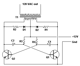
Inverter
Have you ever wanted to run a TV, stereo or other appliance while on the road or camping? Well, this inverter should solve that problem. It takes 12 VDC and steps it up to 120 VAC. The wattage depends on which tansistors you use for Q1 and Q2, as well as how "big" a transformer you use for T1. The inverter can be constructed to supply anywhere from 1 to 1000 (1 KW) watts.
Parts:
| Part | Total Qty. | Description | Substitutions |
| C1, C2 | 2 | 68 uf, 25 V Tantalum Capacitor | |
| R1, R2 | 2 | 10 Ohm, 5 Watt Resistor | |
| R3, R4 | 2 | 180 Ohm, 1 Watt Resistor | |
| D1, D2 | 2 | HEP 154 Silicon Diode | |
| Q1, Q2 | 2 | 2N3055 NPN Transistor (see "Notes") | |
| T1 | 1 | 24V, Center Tapped Transformer (see "Notes") | |
| MISC | 1 | Wire, Case, Receptical (For Output) |
Notes:
1. Q1 and Q2, as well as T1, determine how much wattage the inverter can supply. With Q1,Q2=2N3055 and T1= 15 A, the inverter can supply about 300 watts. Larger transformers and more powerful transistors can be substituted for T1, Q1 and Q2 for more power.
2. The easiest and least expensive way to get a large T1 is to re-wind an old microwave transformer. These transformers are rated at about 1KW and are perfect. Go to a local TV repair shop and dig through the dumpster until you get the largest microwave you can find. The bigger the microwave the bigger transformer. Remove the transformer, being careful not to touch the large high voltage capacitor that might still be charged. If you want, you can test the transformer, but they are usually still good. Now, remove the old 2000 V secondary, being careful not to damage the primary. Leave the primary in tact. Now, wind on 12 turns of wire, twist a loop (center tap), and wind on 12 more turns. The guage of the wire will depend on how much current you plan to have the transformer supply. Enamel covered magnet wire works great for this. Now secure the windings with tape. Thats all there is to it. Remember to use high current transistors for Q1 and Q2. The 2N3055's in the parts list can only handle 15 amps each.
3. Remember, when operating at high wattages, this circuit draws huge amounts of current. Don't let your battery go dead :-).
4. Since this project produces 120 VAC, you must include a fuse and build the project in a case.
5. You must use tantalum capacitors for C1 and C2. Regular electrolytics will overheat and explode. And yes, 68uF is the correct value. There are no substitutions.
6. This circuit can be tricky to get going. Differences in transformers, transistors, parts substitutions or anything else not on this page may cause it to not function.
![]() Also check the conversation about this project at the community. Post you
questions here.
Also check the conversation about this project at the community. Post you
questions here.
Title: Inverter
electronic circuit
Source: www.aaroncake.net
Published on: 2005-02-03
Reads: 1800
Print version: ![]()
Other electronic circuits and schematics from Power
-
Simple Car Battery Charger
-
LASER Power Supply
-
Portable CD Player Adapter For Car
-
120 VAC Lamp Dimmer
-
Fixed Voltage Power Supply
-
Instrument panel lamp dimmer control
-
Ultra low drop linear voltage regulator
-
Ni-Cd Battery Auto Charger
-
NiCd - NiMH Charger
-
AC Current Monitor

