LASER Transmitter/Receiver
This set of two circuits from the basis for a very simple light wave transmitter. A LASER beam is modulated and then aimed at a receiver that demodulates the signal and then presents the information (voice, data, etc..). The whole thing is very easy to build and requires no specialized parts execpt for the LASER itself. LASERs are available from MWK Industries.
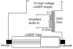
Schematic Of Transmitter
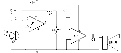
Schematic Of Receiver
Parts:
| Part | Total Qty. | Description | Substitutions |
| C1, C2 | 2 | 0.1uf Ceramic Disc Capacitor | |
| C3 | 1 | 100uf 25V Electrolytic Capacitor | |
| R1 | 1 | 100K Ohm 1/4W Resistor | |
| R2 | 1 | 1M Ohm 1/4W Resistor | |
| R3 | 1 | 10K Pot | |
| Q1 | 1 | NPN Phototransistor | |
| U1 | 1 | 741 Op Amp | |
| U2 | 1 | LM386 Audio Amp | |
| SPKR1 | 1 | 8 Ohm Speaker | |
| T1 | 1 | 8 Ohm:2K Audio Transformer | |
| MISC | 1 | Wire, Board, Knob For R3, LASER Tube and Power Supply |
Notes:
1. In the transmitter schematic, no ballast resistor is shown because most small LASER power supplies already have one built in. Yours may differ, and a resistor may be needed.
2. The receiver should be kept away from bright lights. You may want to put a piece of wax paper in front of Q1 to keep the LASER from swamping it.
3. In order to get any decent amount of modulation, you may need to drive T1 with more then a watt.
4. The circuit can be made to transmit computer data with the use of two modem chips.
Title: LASER Transmitter/Receiver
electronic circuit
Source: www.aaroncake.net
Published on: 2005-02-03
Reads: 1330
Print version: ![]()
Other electronic circuits and schematics from Motor, light and power control
-
73 MHz Hallogene Lamp Radio-Controlled
-
Dome Lamp Dimmer
-
6 Channel Auto Reverse Sequential
-
Sunrise Lamp
-
120VAC Lamp Chaser
-
Expandable 16 Stage LED Sequencer
-
25 Light Sequencer using Xmas lamps
-
Digital Stopwatch 0-60sec
-
Temperature-controlled Fan
-
Super simple stepper motor controller