DC Motor Control Circuit
Notes:
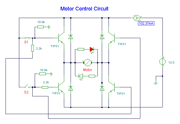
Here, S1 and S2 are normally open , push to close, press button switches. The
diodes can be red or green and are there only to indicate direction. You may
need to alter the TIP31 transistors depending on the motor being used. Remember,
running under load draws more current. This circuit was built to operate a
small motor used for opening and closing a pair of curtains. As an advantage
over automatic closing and opening systems, you have control of how much, or how
little light to let into a room. The four diodes surriunding the motor, are
back EMF diodes. They are chosen to suit the motor. For a 12V motor drawing
1amp under load, I use 1N4001 diodes.
Title: DC Motor Control Circuit
electronic circuit
Source: www.electronics-lab.com
Published on: 2005-02-03
Reads: 2703
Print version: ![]()
Other electronic circuits and schematics from Motor, light and power control
-
220 Volts Flashing Lamps
-
Automatic Room Lights
-
Stepper Motor Controller
-
Simple DC motor PWN speed control
-
Discrete component motor direction controller
-
Light Flasher
-
120VAC Lamp Chaser
-
Digital Stopwatch 0-60sec
-
LED or Lamp Flasher
-
Interfacing 5 volt CMOS to 12 volt/ 25 Watt Loads