Offset nulling
Earlier on it was mentioned that there are two connections to the 741 which are called offset null connections. In most op-amp applications these would not be used, but in certain instances, where the level of the output voltage is of critical importance they are.
When the op-amp has no input voltage applied to it — or, more correctly speaking, the input voltage is 0 V — the output voltage should be the same i.e., 0 V. Under ideal conditions of manufacture this would be so, but as the 741 is a mass-produced device there are inevitable differences in circuit operation and so the output is rarely exactly 0 V. Temperature differences can also create changes in this output voltage level. The difference in the output from 0 V is known as the offset voltage and is usually in the order of just a few millivolts.
Hint:
In the majority of applications this level of offset voltage is no problem and so no action is taken to eliminate it. But the offset null terminals of the 741 may be used to control the level of offset voltage to reduce it to zero.
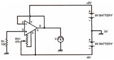
Figure 9.11 An experimental circuit to demonstrate the process of offset nulling
Figure 9.11 shows a circuit which you can build to see the effects of the process of offset nulling, where a potentiometer has been connected between the two offset null terminals with its wiper connected to the negative supply. Adjusting the wiper controls the offset voltage. You’ll see that the circuit is basically a buffer amplifier, like that of Figure 9.9, in which the input voltage to the non-inverting terminal is 0 V.
Figure 9.12 shows the breadboard layout of this offset nulling circuit. The multi-meter should be set to its lowest voltage setting e.g., 0.1 V, and even at this setting you won’t notice much difference in the output voltage. In fact, you probably won’t be able to detect any more than a change of about ±10 millivolts as you adjust the preset resistor.
<< Follow me