Stability built in
The power supplies we’ve seen so far are simple but they do have the drawback that output voltage is never exact — ripple voltage and to a large extent, load current requirements mean that a variation in voltage will always occur. In many practical applications such supplies are adequate, but some applications require a much more stable power supply voltage.
We’ve already seen a device capable of stabilising or regulating power supplies — the zener diode. Figure 7.14 shows the simple zener circuit we first saw last chapter. You’ll remember that the zener diode is reverse biased and maintains a more or less constant voltage across it, even as the input voltage Vin changes. If such a zener circuit is used at the output of a smoothed power supply (say, that of Figure 7.12) then the resultant stabilised power supply will have an output voltage which is much more stable, with a much reduced ripple voltage.
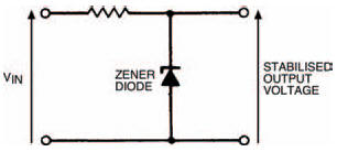
Figure 7.14 A simple zener circuit which can be used with a smoothing circuit to give a greatly reduced ripple voltage
Zener stabilising circuits are suitable when currents of no more than about 50 mA or so are required from the power supply. Above this it’s more usual to build power supplies using stabilising integrated circuits (ICs), specially made for the purpose. Such ICs, commonly called voltage regulators, have diodes and other semiconductors within their bodies which provide the stabilising stage of the power supply. Voltage regulators give an accurate and constant output voltage with extremely small ripple voltages, even with large variations in load current and input voltage. ICs are produced which can provide load current up to about 5 A.
In summary, the power supply principle is summarised in Figure 7.15 in block diagram form. From a 230 V a.c. input voltage, a stabilised d.c. output voltage is produced. This is efficiently done only with the use of diodes in the rectification and stabilisation stages.
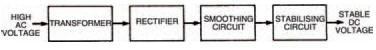
Figure 7.15 A block diagram of a power supply using the circuit stages we have described
<< Filter tips