Filter Tips
The a.c. voltage dividers of Figures 5.5 and 5.12 are normally shown in a slightly different way, as in Figures 5.14(a) and (b). Due to the fact they allow signals of some frequencies to pass through, while filtering out other signal frequencies, they are more commonly called filters.
The filter of Figure 5.14(a) is known as a high-pass filter — because it allows signal frequencies higher than its corner frequency to pass while filtering out signal frequencies lower than its corner frequency.
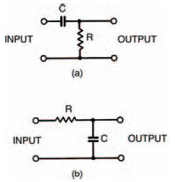
Figure 5.14 The a.c. divider sections of the circuits in Fiqure 5.5 and Figure 5.12
The filter of Figure 5.14(b) is a low-pass filter — yes, you’ve guessed it — because it passes signals with frequencies below its corner frequency, while filtering out higher frequency signals.
Filters are quite useful in a number of areas of electronics. The most obvious example of a low-pass filter is probably the scratch filter sometimes seen on stereo systems. Scratches and surface noise when a record is played, or tape hiss when a cassette tape is played, consist of quite high frequencies; the scratch filter merely filters out these frequencies, leaving the music relatively noise free.
Bass and treble controls of an amplifier are also examples of high- and low-pass filters: a bit more complex than the simple ones we’ve looked at here but following the same general principles.
And that’s about it for this chapter. You can try a few experiments of your own with filters if you want. Just remember that whenever you use your meter to measure voltage across a resistor in a filter, the meter resistance affects the actual value of resistance and can thus drastically affect the reading.
Now try the quiz over the page to check and see if you’ve been able to understand what we’ve been looking at this chapter.
<< Ouch, that hertz