Down to business
Figure 4.2(a) shows the circuit symbol of an ordinary capacitor. As you’ll appreciate, this illustrates the basic capacitor make-up we’ve just seen. Figure 4.2(b), on the other hand, shows the circuit symbol of a specific although very common type of capacitor: the electrolytic capacitor.
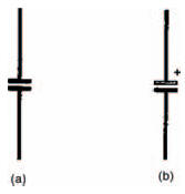
Figure 4.2 Circuit symbols for (a) an ordinary and (b) an electrolytic capacitor
Hint:
The electrolytic capacitor gets its name from the fact that its basic capacitor action is derived through the process of electrolysis when the capacitor is connected into circuit. This electrolytic action means that an electrolytic capacitor must be inserted into circuit the right way round, unlike most other capacitors. We say that electrolytic capacitors are polarised and to show this the circuit symbol has positive (white) and negative (black) plates. Sometimes as we’ve shown, a small positive symbol (+) is drawn beside the electrolytic capacitor’s positive plate, to reinforce this.
In our experiments in this chapter, we’re going to use electrolytic capacitors, not because we like to be awkward, but because the values of capacitance we want are quite high. And electrolytic capacitors are generally the only ones capable of having these values, while keeping to a reasonable size and without being too expensive. Anyway, not to worry, all you have to do is remember to put the capacitors into circuit the right way round.
You can make sure of this, as all electrolytic capacitors have some kind of marking on them which identifies positive and negative plates. Figure 4.3 shows two types of fairly typical electrolytic capacitors. One, on the left, has what is called an axial body, where the connecting leads come out from each end. One end, the positive plate end, generally has a ridge around it and sometimes is marked with positive symbols (as mine is). Sometimes, the negative plate end has a black band around it, or negative symbols.
The capacitor on the right has a radial body, where both leads come out from one end. Again, however, one or sometimes both of the leads will be identified by polarity markings on the body.
Whatever type of electrolytic capacitor we actually use in circuits, we shall show the capacitor in a breadboard layout diagram as an axial type. This is purely to make it obvious (due to the ridged positive plate end) which lead is which. Both types are, in fact, interchangeable as long as the correct polarity is observed, and voltage rating (that is, the maximum voltage which can be safely applied across its leads — usually written on an electrolytic capacitor’s body) isn’t exceeded.
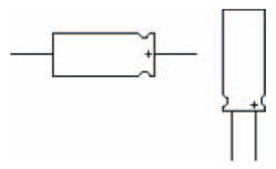
Figure 4.3 (Left) an axial capacitor and (right) a radial capacitor
<< Capacitors