All aboard
A breadboard is extremely useful. With a breadboard you can construct circuits in a temporary form, changing components if required, before committing them to a permanent circuit board. This is of most benefit if you are designing the circuit from scratch and have to change components often.
If you are following a book like Starting Electronics, however, a breadboard is even more useful. This is because the many circuits given in the book can be built up experimentally, tested, then dismantled, so that the components may be used again and again. I’ll be giving you many such experimental circuits and, although I’ll also give you good descriptions of the circuits, there’s nothing like building-it-yourself to find out how a circuit works. So, I recommend you get the best kind of breadboard you can find — it’s worth it in the long run.
There are many varieties of breadboard. All of the better ones consist basically of a moulded plastic body which has a number of holes in the top surface, through which component leads may be easily pushed. Underneath each hole is a clip mechanism, which holds the component lead tight enough so that it can’t fall out. Figure 2.1 gives the idea. The clip forms a good electrical contact, yet allows the lead to be pulled out without damage.
Generally, the clips are interconnected in groups, so that by pushing leads of two different components into two holes of one group you have made an electrical contact between the two leads. In this way the component leads don’t have to physically touch above the surface of the breadboard to make electrical contact.
Differences lie between breadboards in the spacings and positionings of the holes, and the number of holes in each group. The majority of breadboards have hole spacings of about 2.5 mm (actually 0.1 in — which is the exact hole spacing required by a particular type of electronic component: the dual-in-line integrated circuit — I’ll talk about this soon) which is fine for general-purpose use, so the only things you have to choose between are the numbers of holes in groups, the size of the breadboard and the layout (that is, where the groups are) on the breadboard.
Because there are so many different types of breadboard available, we don’t specify a standard type to use in this book. So the choice of what to buy is up to you. We do, however, show circuits on a basic breadboard which is a fairly common layout. So, any circuits we show you to build on this breadboard can also be built on any similar quality breadboard, but you may have to adjust the actual practical circuit layout to suit.
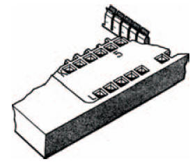
Figure 2.1 The interior of a breadboard, showing the contacts
Photo 2.1 shows a photograph of the breadboard we use throughout this book, in which you can see the top surface with all the component holes. Photo 2.2 shows the inside of the breadboard, with component lead clips interconnected into groups. The groups of clips are organised as two rows, the closest holes being 7.5 mm — (not just by coincidence the distance between the rows of pins of a dual-in-line integrated circuit package) apart.
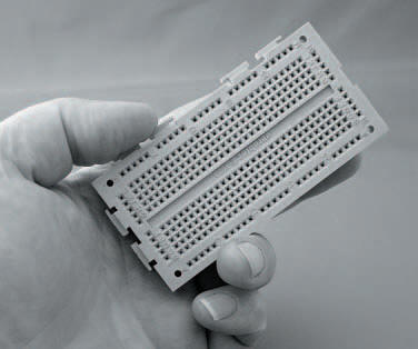
Photo 2.1 A typical breadboard
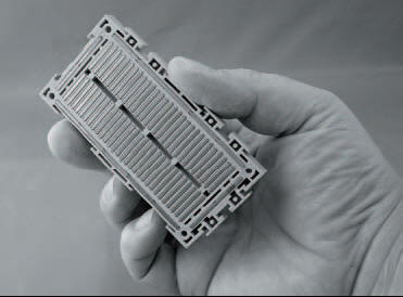
Photo 2.2 Inside breadboard, showing component clips interconnected in groups
Hint:
The theoretical breadboard used for artwork layout purposes in this book is specified with a total of 550 contacts arranged in a main matrix of two blocks of 47 rows of five interconnected sockets, and a row of 40 interconnected sockets down each side of the main matrix. Such a theoretical block will hold upto six 14-pin or nine 8-pin dual-in-line integrated circuit packages, together with their ancillary components.
Remember though, that you may need to adapt the theoretical circuit layout to suit whichever particular breadboard you buy.
<< On the boards