LED Photo Sensor
Here's a circuit that takes advantage of the photo-voltaic voltage of an ordinary LED. The LED voltage is buffered by a junction FET transistor and then applied to the inverting input of an op-amp with a gain of about 20. This produces a change of about 5 volts at the output from darkness to bright light. The 100K potentiometer can be set so that the output is around 7 volts in darkness and falls to about 2 volts in bright light.
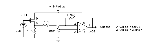
LED Photo Sensor circuit
Title: LED Photo Sensor
electronic circuit
Source: unknown
Published on: 2007-07-21
Reads: 3700
Print version: ![]()
Other electronic circuits and schematics from Motor, light and power control
-
Alternating Flasher
-
73 MHz Hallogene Lamp Radio-Controlled
-
12VDC Fluorescent Lamp Driver
-
Temperature-controlled Fan
-
LEDs or Lamps Sequencer
-
6 Channel Auto Reverse Sequential
-
Brightness Control for small Lamps
-
IR Remote Control Jammer
-
Optical toggle switch using a single Chip
-
1.5 Hour Lamp Fader (Sunset Lamp)