Integrated circuits
But the big advantage of transistors, especially tiny transistors, is that many of them may be integrated into a single circuit, which is itself still very small. To give you an idea of what we’re talking about, modern integrated circuits (well, what else would you call them?) have been made with over a quarter of a million transistors, all fitting onto one small silicon chip only about forty square millimetres or so! Now this sort of integration represents the ultimate in human achievement, remember, but processes are being improved every year and integrated circuits with only hundreds of thousands of integrated transistors are now commonplace. Because of this it stands to reason that we have to come to grips with integrated circuits, they’re here to stay and there’s no point in being shy. So the final chapters of this epic saga are devoted to integrated circuits.
The integrated circuit which we are going to play with this chapter is an analogue integrated circuit (let’s cut all these long words out and call them by their abbreviation — IC). Just as there are analogue and digital circuits which transistors are used in, so there are analogue and digital ICs. This IC just happens to be analogue, but there are digital ones too — the 555 (which we’ve already seen) is actually an example. In IC terms the IC in this chapter is a comparatively simple IC, having only around twenty transistors in all; nevertheless it is an extremely versatile IC and is probably the most commonly used IC of all time.
Generally it’s called the 741, referring to the numbers which are printed on the top of the IC body — see Photo 9.1. If you look at your IC you’ll see that it also has some letters associated with the number 741. These letters e.g., LM, SN, μ, MC, refer to the manufacturer of the device and bear no relevance to the internal circuit, which is the same in all cases. An SN741 is identical in performance to a μ741. Other letters printed on the top of the IC refer to other things such as batch number, date of manufacture etc. Whatever is printed on the top of the IC, as long as it is a 741 there’s normally no problem and it’ll work in all the circuits we’re going to look at now.
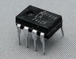
Photo 9.1 Our subject: a 741 op-amp
You’ll notice that the 741 is identical in physical appearance to the other IC we’ve already looked at, the 555. Like the 555, the 741 is housed in an 8-pin DIL (dual-in-line) body. But although the shape’s the same, the internal circuit isn’t. Other versions of the 741 exist, in different body styles, but the 8-pin DIL version is by far the most popular.
The 741’s internal circuit is shown in Figure 9.1. Its circuit symbol is shown in Figure 9.2. From this you can see that the circuit has two inputs, marked + and –. Technically speaking these are called the non-inverting and inverting inputs. The circuit has one output and two inputs for power supply connection. There are also two other connectors to the circuit, known as offset null connections; controlling the voltages of these inputs, controls the voltage level of the output — you’ll find out how these connections work soon. They are not used in every circuit which the 741 is used in.
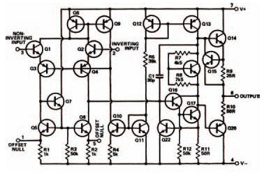
Figure 9.1 The internal circuit of the 741: a mere 22 transistors
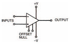
Figure 9.2 The circuit symbol for a 741
The internal layout of the 8-pin DIL version of the 741 is shown in Figure 9.3. Now, each input and output of the op-amp is associated with a particular pin of the DlL body. This means that we can redraw the circuit symbol of the 741, as in Figure 9.4, with the corresponding pin numbers at each connection.
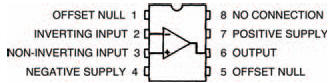
Figure 9.3 The internal layout of an 8-pin DIL-packed 741
Note that these pin numbers are only correct when we deal with the 8-pin DIL version, however, and any other versions would have different pin numbers. We’ll show the 8-pin DIL pin numbers with any circuit diagram we show here, though, as we assume that you will use this version.
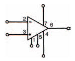
Figure 9.4 The symbol in Figure 9.2, with the pin numbers included
Apart from the 741, there are a small number of other components you’ll also need for the circuits in this chapter. These are:
- 2 x 10 kΩ resistors
- 3 x 47 kΩ resistors
- 1 x 22 kΩ resistor
- 1 x 47 kΩ miniature horizontal preset