Practically there
Now that we’ve looked at the theory behind current and voltage measurement, let’s go on and build a few circuits to put it into practice. Figure 3.10 shows the breadboard layout of the circuit of Figure 3.6, where a single resistor is connected in series with a multi-meter and a battery. With this circuit we can actually prove Ohm’s law. The procedure is as follows:
- set the meter’s range switch to a current range — the highest one, say, 10 A,
- insert a resistor (of say 1k5) into the breadboard, and connect the battery leads,
- touch the multi-meter leads to the points indicated.
You will probably see the pointer of the multi-meter move (but only just) as you complete step 3. The range you have set the multi-meter to is too high — the current is obviously a lot smaller than this range, so turn down the range switch (to, say, the range nearest to 250 mA) and do step 3 again.
This time the pointer should move just a bit further, but still not enough to allow an accurate reading. Turn down the range switch again, this time to, say, the 25 mA range and repeat step 3. Now you should get an adequate reading, which should be 6 mA give or take small experimental errors.
Is this right? Let’s compare it to the expression of Ohm’s law:

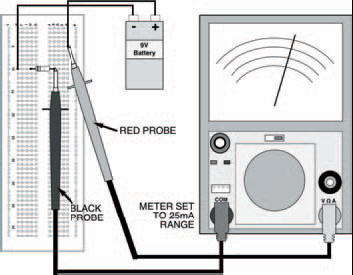
Figure 3.10 A breadboard layout for the circuit of Figure 3.6: the meter is in series with the resistor; only the meter itself makes the circuit complete
If we insert known values of voltage and resistance into this we obtain:

Not bad, eh? We’ve proved Ohm’s law!
You can try this again using different values of resistor if you wish, but don’t use any resistors lower than about 500 Ω as you won’t get an accurate reading, because the battery can’t supply currents of more than just a few mA. Even if it could the resistor would overheat due to the current flowing through it.
In all cases where the battery is able to supply the current demanded by the resistor, the expression for Ohm’s law will hold true.
Take note
Make sure that you start a new measurement with the range switch set to the highest range and step down. This is a good practice to get into, because it may prevent damage to the multimeter by excessive currents. Even though circuits we look at in Starting Electronics will rarely have such high currents through them, there may be a time when you want to measure an unknown current or voltage in another circuit; if you don’t start at the highest range — zap — your multi-meter could be irreparably damaged.
Hint:
The scale you must use to read any measurement from, depends on the range indicated by the meter’s range switch. When the range switch points, say, to the 10 A range, the scale with the highest value of 10 should be used and any reading taken represents the current value. When the range switch points to, say, the 250 mA range, on the other hand, (and also the other two ranges 2.5 mA and 25 mA), the scale with the highest value of 25 should be used. It all sounds tricky doesn’t it? Well, don’t worry, once you’ve seen how to do it, you’ll be taking measurements easily and quickly, just like a professional.
Note that current (and voltage) scales read in the opposite direction to the resistance scale we used in the last chapter, and they are linear. This makes them considerably easier to use than resistance scales and they are also more accurate as you can more easily judge a value if the pointer falls between actual marks on the scale.
<< A meter with potential