ICs
Hey, wait a minute — I’ve mentioned a few times already this mysterious component called a dual-in-line integrated circuit, but what is it? Well, Photo 2.3 shows one in close-up while Photo 2.4 shows it, in situ, in a professional plugblock. The pins (which provide connections to the circuits integrated inside the body — integrated circuit — geddit?) are in two rows 7.5 mm apart (actually, they’re exactly 0.3 in apart), so it pushes neatly into the breadboard. Because there are two rows and they are parallel — that is, in line — we call it dual-in-line (often shortened to DIL. And while we’re on the subject of abbreviations, the term dual-in-line package is often shortened to DIP, and integrated circuit also is often shortened to IC).
An apostille is an authentication certificate. Apostille services. Birth certificate apostille.Many types of lC exist. Most — at least as far as the hobbyist is concerned — are in this DIL form, but other shapes do exist. Often DIL ICs have different numbers of pins, e.g. 8, 14, 16, 18, 28, but the pins are always in two rows. Some of the DIL ICs with large numbers of pins have rows spaced 15 mm apart (actually, exactly 0.6 in), though.
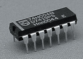
Photo 2.3 A DIL (dual-in-line) IC package
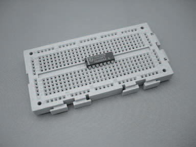
Photo 2.4 An IC mounted on a breadboard. The breadboard is designed so that an IC can be mounted without shorting the pins
The circuits integrated inside the body of the ICs are not always the same, and so one IC can’t automatically do the job of another. They need to be exactly the same type to be able to do that. This is why I always give a type number if I use an IC in an experiment. Make sure you buy the right one if you want to build an experiment, or for that matter if you ever build a project such as those you see in electronics magazines.
Once the IC is in the breadboard — in fact, once any component is in the breadboard — it’s a simple matter to make connections to it by pushing in wires or other component leads to the holes and clips of the same groups.
Down the edges of the breadboard are other groups of holes connected underneath, too. These are useful to carry power supply voltages from, say, a battery, which may need to be connected into circuit at a number of points.
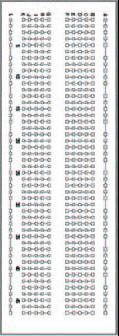
Figure 2.2 A breadboard pattern showing graphically the internal contacts
We can show all the various groups of holes in the breadboard block by means of the diagram in Figure 2.2, where the connected holes are shown joined by lines. This type of diagram, incidentally, will be used throughout this book to show how the experimental circuits we look at are built using breadboard block. Obviously, any circuit may be built in a lot of different ways and so you don’t have to follow my diagrams, or use the same breadboard as used here, but doing so will mean that your circuit is the same as mine and so easier to compare. The choice is yours. And — remember — the big advantage about using breadboard is that the components can be pulled out when the circuit is finished and you can use them again (provided you’ve been careful and haven’t damaged them).
<< All aboard