
LCD Module Control with PC
This simple circuit controls a popular 2-line x 16-character LCD by a PC via printer port. It doesn't use the Bi-directional feature found on newer printer ports, thus it should work with most, if no all Parallel Ports. These LCD Modules are very common these days, and are quite simple to work with, as all the logic required to run them is on board.
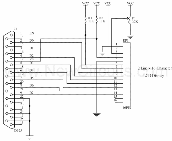
The LCD panel's Enable and Register Select is connected to the Control Port. The Control Port is an open collector / open drain output. While most Parallel Ports have internal pull-up resistors, there are a few which don't. Therefore by incorporating the two 10K external pull up resistors, the circuit is more portable for a wider range of computers, some of which may have no internal pull up resistors. The 10k Potentiometer controls the contrast of the LCD panel. The software source code has been written in Borland C++ .
Source Code (1KB)
Title: LCD Module Control with PC
electronic circuit
Source: unknown
Published on: 2005-08-27
Reads: 1187
Print version: 
Other electronic circuits and schematics from PC related
-
PC based Frequency Meter
-
The 8Way Relay Board
-
Build your own printer cable LCD Display
-
LCD2LPT with LIRC
-
VGA to TV Scart
-
7 segment rolling display using PC
-
RJ45 Network card to IR communication
-
3-Axis Stepper Controller
-
RS-232 Laser Transceiver
-
4 - Channel Digital Logic Analyzer and 5 Channel Digital Oscilloscope by using PC Parallel Port